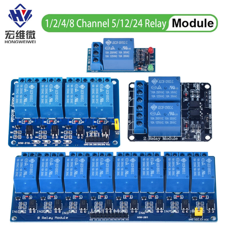
What Is the 5V Relay Module Board?
The module is a small carrier board: an input stage (resistor → optocoupler → transistor), a Songle SRD-05VDC-SL-C relay, LEDs, screw terminals, and a power-select jumper. The relay is the part whose ratings matter, and the part number says three things: `S` = sealed, `L` = high-sensitivity 0.36W coil (71.4mA at 5V, per the coil data chart), `C` = 1 Form C — a single-pole double-throw contact with NO, NC, and COM terminals.
The optocoupler (a PC817-class part) is fed by the GPIO through a 1k input resistor; the module documentation puts the driver current at 15–20 mA per channel, which every ESP32 GPIO supplies comfortably. At $2 for a single channel, it is the cheapest way to add physical switching to a project — and the real money is in smart home installations, where the honest spec table below is exactly what separates a professional quote from a beginner's guess.
What Do the Listings Get Wrong About the Ratings?
Almost every AliExpress listing and even some module datasheets print "10A 250VAC / 30VDC". Next to the Songle datasheet, that headline fails on three counts — and each one matters for what you promise a paying client:
| Listings say | Datasheet says (§7, Form C — this part) | Why the difference matters |
|---|---|---|
| 10A at 250VAC | 10A at 125VAC; 7A at 240VAC. Max switching voltage is 250VAC, but the 10A/240VAC headline belongs to the Form A (NO-only) variant | Voltage and current maxima do not coexist; and this part is the C form, not the A |
| 30VDC | 28VDC | Marketing rounding up the DC rating |
| "10A" unqualified | 3A for inductive loads at 120/28VAC (cosΦ=0.4, L/R=7ms) | Fans, pumps, and compressors are inductive: about one-third of the resistive rating |
The same §7 table also caps maximum switching power at 800VA (Form C), lists AgCdO contacts, and — on the life-expectancy row — quotes 10⁷ mechanical / 10⁵ electrical minimum operations, with the electrical figure attached to a test condition rather than a stated contact load. Quote it that way, not as a load-rating promise.
The derate the module documentation never prints
The relay manufacturer publishes an inductive-load rating of 3A for this Form-C part. The module vendors' own documents stop at the flat "AC250V 10A" headline and say nothing about inductive loads, snubbers, or contact arcing — that silence is documented as fact (their features lists end at the headline). When a client wants a ceiling fan or a pump switched, the honest quote is built on 3A, not 10A.
How Does the Relay Module Work?
The trigger is active-LOW: the input pin is the cathode side of the opto-LED, which is fed from VCC through the input resistor — so pulling your GPIO LOW completes the LED circuit and energizes the relay; HIGH leaves it off. Two vendor documents agree: the Handson 4-channel guide states verbatim "The digital inputs from Arduino are Active LOW: The relay actuates and LED lights when the input pin is LOW," and SunFounder's own sample code activates a relay with digitalWrite(pin, LOW). One SunFounder sentence ("when input is at low level, the relay is off") contradicts its own code sample — the code and the Handson guide agree, and that is where this review stands.
Per channel the signal path is: input resistor → PC817 optocoupler → NPN transistor (driven low-side) → relay coil, with a flyback diode across the coil. That diode protects the transistor from the coil's back-EMF — it does nothing for the contacts on the load side, which is why the inductive derate above still applies.
The JD-VCC jumper, and why it matters for ESP32 builds
The jumper bridges the relay-coil supply (JD-VCC) to the logic-side VCC. Jumper on: one 5V rail feeds everything — convenient, no true isolation, and the supply must carry all four coils at once: 4 × 71.4mA ≈ 286mA (≈317mA worst-case at the coil's −10% resistance tolerance), plus up to ~80mA of opto-LED current — about 366mA total, well above the module's own "greater than 100mA" floor line. Jumper off: JD-VCC gets its own supply (or the ESP32 dev board's 5V pin from its USB input), the ESP32's 3.3V logic feeds only the opto LEDs (~15–20mA per channel), and the logic side is galvanically isolated from the coil side — the documentation's own recipe for Raspberry Pi and other 3.3V controllers, which also works unchanged for the ESP32.
Key Features (each one sourced)
- Optocoupler isolation (PC817-class) — CTR min 50% at IF=5mA per Sharp's datasheet; 5kV input-output isolation
- Form C contacts — NO, NC, and COM on the screw terminal, so a "lights on when relay off" failsafe is free
- Active-LOW trigger — documented in vendor schematics and code, not forum folklore; a minority of modules ship high-trigger or with an H/L jumper, so check yours
- LED indicators — power plus per-channel state
- Coil data — 5VDC, 71.4mA, 70Ω ±10% (0.36W high-sensitivity variant; the current revision lists 69.4Ω — both named in the datasheet lineage)
- Contact endurance — 10⁷ mechanical / 10⁵ electrical minimum operations, with the electrical figure quoted only under its datasheet test condition
What Are the Technical Specs?
How to Build a Smart Home Installation Business
Small homeowners want smart lighting, automated fans, and remote-controlled locks but can't afford $1,000+ commercial systems. You can install a custom ESP32 + relay system for a fraction of that cost. The arithmetic below is a planning scenario, not a recorded sale — your buy price and the local price you can charge are the two numbers only the market settles, so edit both before quoting a client.
Installation Package
- ESP32 controller — $5
- 4-channel relay module — $3
- Power supply — $3
- Enclosure + wiring — $5
- Your firmware + setup — $150–200 labor
Total hardware: ~$16. Client charge: $300–500 per room. That's $284–484 profit per installation.
Should You Buy the 5V Relay Module?
Unit Economics — Smart Home Installation
profit per room installation
| ESP32 controller | $5 |
| 4-channel relay module | $3 |
| Power supply | $3 |
| Enclosure + wiring | $5 |
| Total hardware cost | $16 |
| Your labor (3-4 hours) | $150–200 |
| Total cost per install | $166–216 |
| Client charge | $300–500 |
| Profit per install | $284–484 |
✅ Buy
The foundation of a smart home installation business. At $2 per relay with $284–484 profit per install, this is one of the highest-margin IoT plays on AliExpress. Start with one room, build your portfolio, then scale.
How This Compares
| Feature | This Product | Commercial Alternative |
|---|---|---|
| Price | $2 | $20-50 |
| DIY Required | Yes | No |
| Profit Potential | High | N/A |
Where to Buy
Search "5V relay module optocoupler" or "4 channel relay module Arduino" on AliExpress. Expect ~$1-4 depending on channel count. Buy from sellers with 95%+ ratings.
Affiliate link — we earn a small commission at no extra cost to you.
What Do People Ask About the 5V Relay Module Board?
What is a 5V relay module board?
A $2 carrier board with an opto-isolated input stage and a Songle SRD-05VDC-SL-C relay (Form C/SPDT). Its contacts are rated 10A 125VAC / 7A 240VAC / 7A 28VDC (resistive), and it triggers on LOW per the module schematics.
How much money can you make with smart home installations?
Per the planning scenario on this page: about $16 of hardware per room against a $300–500 client charge models $284–484 profit per room — a scenario, not a recorded sale. Your supplier quotes and your local prices are the inputs that make it real.
What can you control with relay modules?
Resistive loads within the Form-C ratings: LED lighting, water heaters elements, kettles under 7A at 240VAC. For inductive loads — fans, pumps, compressors — the Songle datasheet derates the Form C contacts to 3A, which is the number that should govern those quotes. Mains-voltage work belongs to licensed electricians where local code requires one.
Where can I buy 5V relay modules?
Available on AliExpress for ~$1-4 depending on channel count. Search '5V relay module optocoupler' and buy from sellers with 95%+ positive ratings.
📬 Newsletter
One Bench-Tested Hardware Side Hustle. Every Tuesday.
Real teardowns, real profit math, real businesses. No fluff. No spam.
Join 847 makers. Unsubscribe anytime. Powered by Buttondown.
Done-for-You Playbook
Smart Home Installation — Complete Business Starter Kit
Everything you need to actually build this business — sourcing links, pricing calculators, client templates, and a 30-day action plan. Skip the guesswork.
📅 Last reviewed: September 2026 · Prices may vary